Sunday, July 10, 2016

Module 09 - Remote Sensing


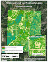
 In module 9 we classified data gathered with remote sensing techniques in two ways: unsupervised and supervised.

In unsupervised classification, we let the software classify pixels into a number of predetermined classes. The downside of this type of classification is that number of categories can overlap. Also some vastly different features may be assigned into the same category, because the shade and tone of their pixels is identical, or nearly so. In case of my unsupervised classification, ArcMap combined water and smooth surfaces such as roof tops into one category.

In supervised classification, we determine a number of points on the raster image, and assign each point a predetermined category (grass, trees, pavement, etc.). We then let the software process all the pixels, and assign them into the predetermined categories. This is still not without issues, as my buildings category and pavement/bare ground categories got combined, but there was a lot less redundant classification.

Monday, July 4, 2016

Module 08- 3D Modeling

In module 8 we created a 3d image of subsurface soil horizons. This process involved interpolating depth data from the shovel test information to create raster files representing elevation of each soil horizon. Then, using ArcScene, we displayed those rasters in a 3d image. To make the image easier to read, we increased the vertical scale, this created a comfortable distance between layers.

When looking at the shovel test data, we split it into three separate layers, one for each horizon, and assigned each horizon a different color. In both Fig 2 and 3 yellow represents A horizon, green B horizon, and purple C horizon.

Figure 4 is missing A horizon because there was no data associated with the given shapefile. While surface data may be available, it would most likely be inaccurate, because the initial data was not gathered from a site datum point, but from the surface. And depending on the region, surface can quickly change for many reasons, such as weather, land usage, etc.
Fig 2. Shovel Test data, divided into soil horizons.
Fig 1. Project area boundaries, horizontal and vertical.


Fig 3. Proposed subsurface line in the project area.
Fig 4. Soil horizons: B on top, C on the bottom.